✈ Free-shipping on orders over $49


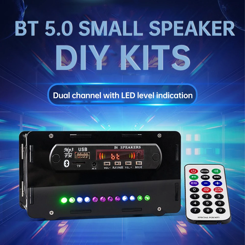
FM Radio DIY Electronics Kit Bluetooth 5.0 Speaker with Voice-activated Level Indicator DIY Electronics Kit DC5V Bluetooth Speak
$29.99 USD$37.29 USD20% off
Color: Transparent shell


Discount only available in
Features:
1.4.8~6.0G broadband FM audio/video synchronized reception, ensure HD smooth transmission
2.Small size SMD package (28×23×3 mm), easy to integrate various devices
3. Low power consumption design (5V 170mA), saving energy and prolonging usage time
4. High reception sensitivity (-90dBm), signal stability, strong anti-interference
5. Built-in frequency phase-locked loop, providing high stability and accurate reception
Parameter:
Product name: RX5808 wireless audio and video receiver module
Supply voltage: 3.5~5.5V
Power supply current: 170mA
Power supply ripple voltage: 10mVpp (Max 25mVpp)
Wideband: 4.8~6.0GHz
Receiving frequency: 5725~5865MHz; 8 channels
Frequency control: Built-in frequency phase-locked loop
AV Output: Directly output analog audio and video signals
Power Consumption: 5V 170mA
Receiving sensitivity: -90dBm
Operating temperature: -20~70°C (only the module itself, not other parts)
Small size SMD package: 28×23×3mm
Package include:
Bluetooth speaker kit x 1
Description:
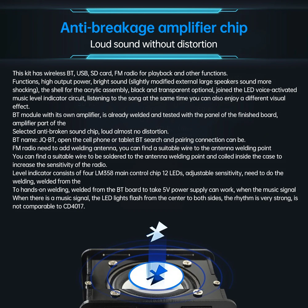
Bluetooth name: JQ-BT, open the cell phone or tablet Bluetooth search and pairing connection can be. fm radio need to add welding antenna, you can find a suitable wire welded to the antenna welding point, disk in the chassis in order to increase the radio sensitivity.
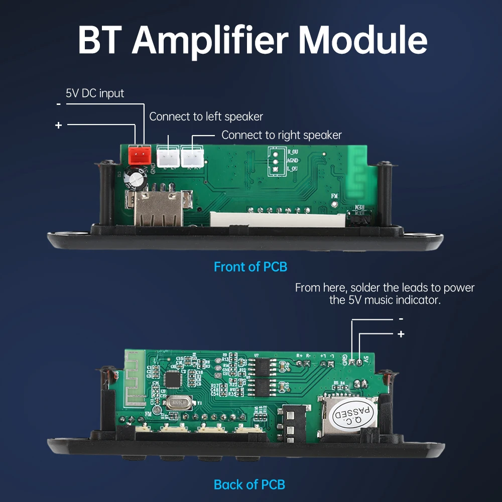
Level indicator consists of four LM358 main control chip 12 LEDs, adjustable sensitivity, need to weld, welded from the bluetooth board to take 5V power supply can work, when there is a music signal LED lights from the center to the two sides of the blinking.
Welding methods and precautions:
The acrylic shell has a protective film, tear off the protective film before assembling, and figure out the position of each board, and then install the speakers, circuit boards, and finally assembling.
Adjustable resistors for adjusting sensitivity are welded on the back of the PCB and exposed after mounting the shell, so that it is easy to adjust the sensitivity at any time.
Components should be welded from short to high, pay attention to distinguish between positive and negative poles. Electrolytic capacitors, light-emitting diode polarity: long foot is positive, short foot is negative.
Welding is completed to fully check whether there is a false weld or short circuit, to confirm that there is no error and then power on the test.
The positive and negative poles of the power supply must not be reversed, otherwise the chip will be burned when the power is turned on.